Modem Eliminators
MODEM ELIMINATORS do just what their name implies. They eliminate modems...or at least they eliminate the need for modems in some cases.Any computer or piece of internetworking equipment with a synchronous DTE communications interface is designed to be cabled directly to a modem. It is dependent upon the modem for the clocking used to transfer synchronous data.Two pieces of equipment having synchronous DTE communication ports cannot be cabled directly together without a clock source...even if the equipment is sitting right next to each other. This is where a modem eliminator provides its solution. These same two pieces of equipment can be connected together by inserting the modem eliminator as the midpoint of their RS232 or V.35 cabling.This type of direct cabling is generally limited to distances of between 50 and 100 feet. The communication ports on both pieces of equipment are provided a clock source and think they are talking to a modem, when in fact, they are talking to each other.A single modem eliminator makes this possible. For equipment that is in a proximity that allows for this direct cabling, the modem eliminator reduces the expense and the clutter of having to use back-to-back modems to implement this synchronous connection.
Modem Eliminator Series
 The Modem Eliminator (ME) Series is a family of dual-port connectivity devices designed to facilitate communications between two pieces of synchronous end-user equipment that are in a proximity that allows for direct cabling. The modem eliminator exhibits a DCE interface on both of its communication ports and appears as a modem to both end-users. It provides the handshaking, clock source and signal levels necessary to satisfy the synchronous interface requirements of the equipment attached to both ports. It allows for the transmission and receipt of synchronous data between the attached equipment. Mainframe computers, front-end processors, controllers, routers, switches and other internetworking equipment exhibit a DTE interface which is designed to be cabled directly to the DCE interface of a modem or modem eliminator.
The Modem Eliminator Series is comprised of 5 models which offer different clocking speeds and physical connectors. The ME-2 is the low speed model that offers an RS232 I/F and generates ten user-selectable clock speeds between 1200 bps and 38.4 Kbps. The ME-3, ME-4 and ME-6 support much higher clock speeds and make use of the industry standard V.35 I/F for high speed comm lines. The ME-3 generates ten user-selectable fractional T1 clock speeds between 19.2 Kbps and 512 Kbps. The ME-4 offers the selection of either T1 or E1 clock speeds, and the ME-6 offers the selection of either T2 or E2. The ME-8 offers an X.21 I/F and generates ten user-selectable fractional E1 clock speeds between 56Kbps and 2.048Mbps (E1).
All models of Modem Eliminators are available in both stand-alone and rackmount versions. The stand-alone versions include a metal case with internal AC power supply that is switchable between 115/230 VAC @ 50/60 Hz. The single-width rackmount versions mount in, and draw their power from, DEI Universal Mount Chassis (UMC) card cages. Rackmount modem eliminators can be installed in the UMC-3, UMC-5 and UMC-6 Rackmount Chassis, which hold up to 15 cards... and also in the TRI-PAK Space Saver Chassis, which holds to to 3 cards.
RS232 and V.35Modem Eliminators can operate in either half or full-duplex modes. In half-duplex operation, Clear-to-Send (CTS) on each comm port follows Request-to-Send (RTS) from that same comm port after a user-defined (strapped) delay period. The Carrier Detect (CO) signal on each comm port follows the RTS signal from the opposite comm port. In full-duplex operation, RTS is strapped as always ON, and so, CTS and CO also respond as always ON (as described above). Data-Set-Ready (DSR) on each comm port can be strapped as always ON, or so that it follows Data-Terminal-Ready (DTR) from the opposite comm port.
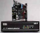
The front panels on DEI RS232 and V.35 Modem Eliminators include LED indicators that represent the Transmit Data (TXD) and Carrier Detect (CO) interface signals from both DCE ports. The TXD indicators reflect the activity of data arriving at each port from attached end-user equipment. The CO indicator of each port reflects the state of the RTS signal from the opposite port.
The ME-8 X.21 Modem Eliminator is similar in design to the RS232 and V.35 models. It supports the Control and Indication X.21 interface handshaking signals which can be used to emulate half or full-duplex operation. The Indication signal on each comm port can be strapped as always ON, or so that it follows the Control signal from the opposite comm port. The ME-8 front panel includes LED indicators that represent the Transmit
Modem eliminators are often used in test environments where new equipment needs to be staged and tested in close proximity prior to being introduced into a live network. Their most traditional role was in facilitating high speed communication links between computers or controllers. More recently, they have facilitated very high speed communication links between routers, switches and other internetworking equipment typically found in large data centers.
We offer our services to modify the form-factor or bit-rates of our off-the-shelf modem eliminators, or even to design new equipment to meet the individual needs of our customers.
|
| Model | Interface | Data Rates |
| ME-2 (R) | RS232 (DB25 Female) | 1.2, 2.4, 3.6, 4.8, 7.2, 9.6, 14.4, 16.8, 19.2, 38.4Kbps. |
| ME-3(R) | V.35 (M34 Female) | 19.2, 38.4, 56, 64, 112, 128, 224, 256, 448, 512Kbps. |
| ME-4(R) | V.35 (M34 Female) | T1 (1.544Mbps) or E1 (2.048Mbps) |
| ME-6(R) | V.35 (M34 Female) | T2 (6.176Mbps) or E2 (8.192Mbps) |
| ME-8(R) | X.21 (DB15 Female) | 56, 64, 112, 128, 224, 256, 448, 512Kbps
1.024Mbps and 2.048Mbps |
